12th October 2025
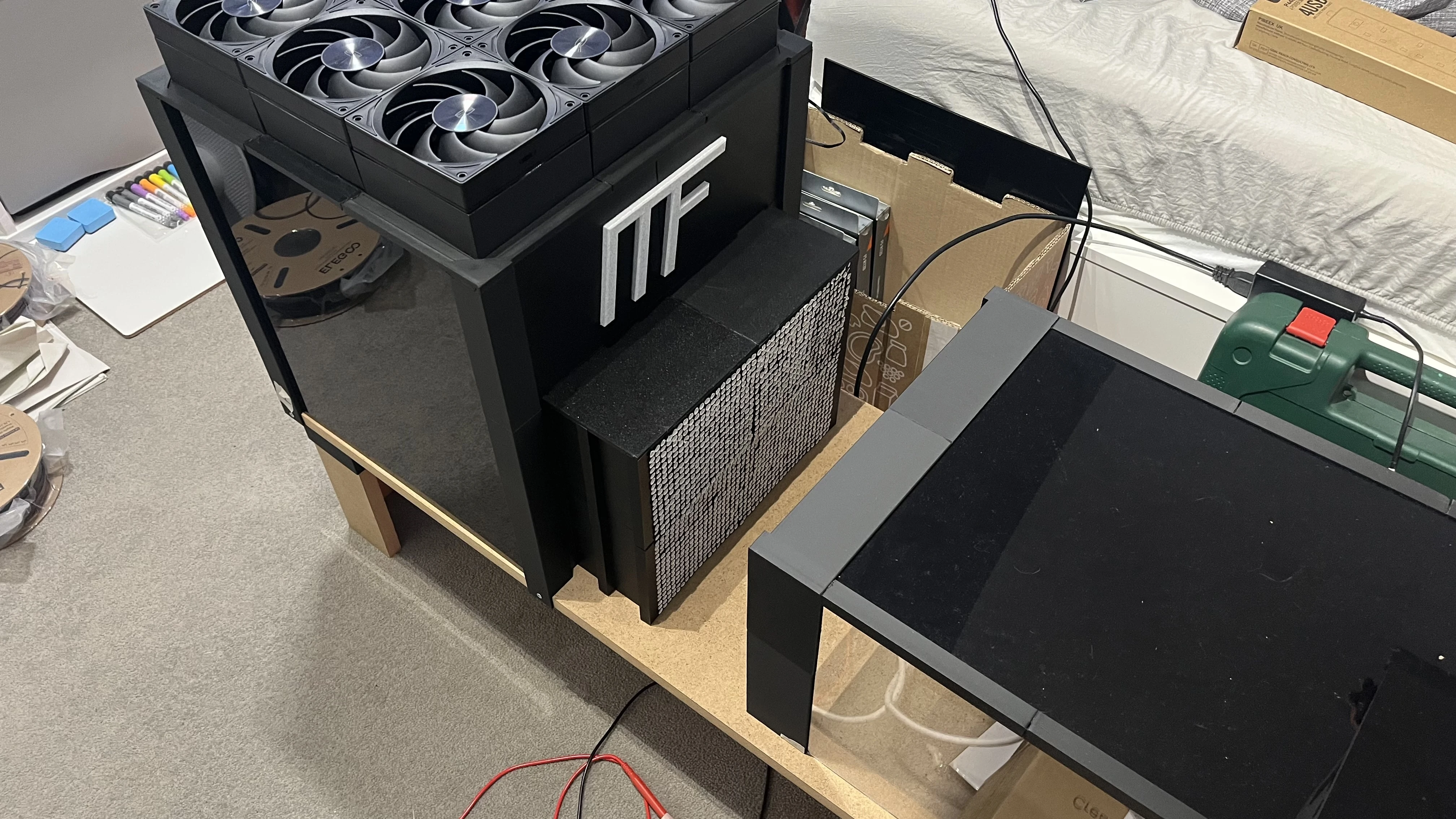
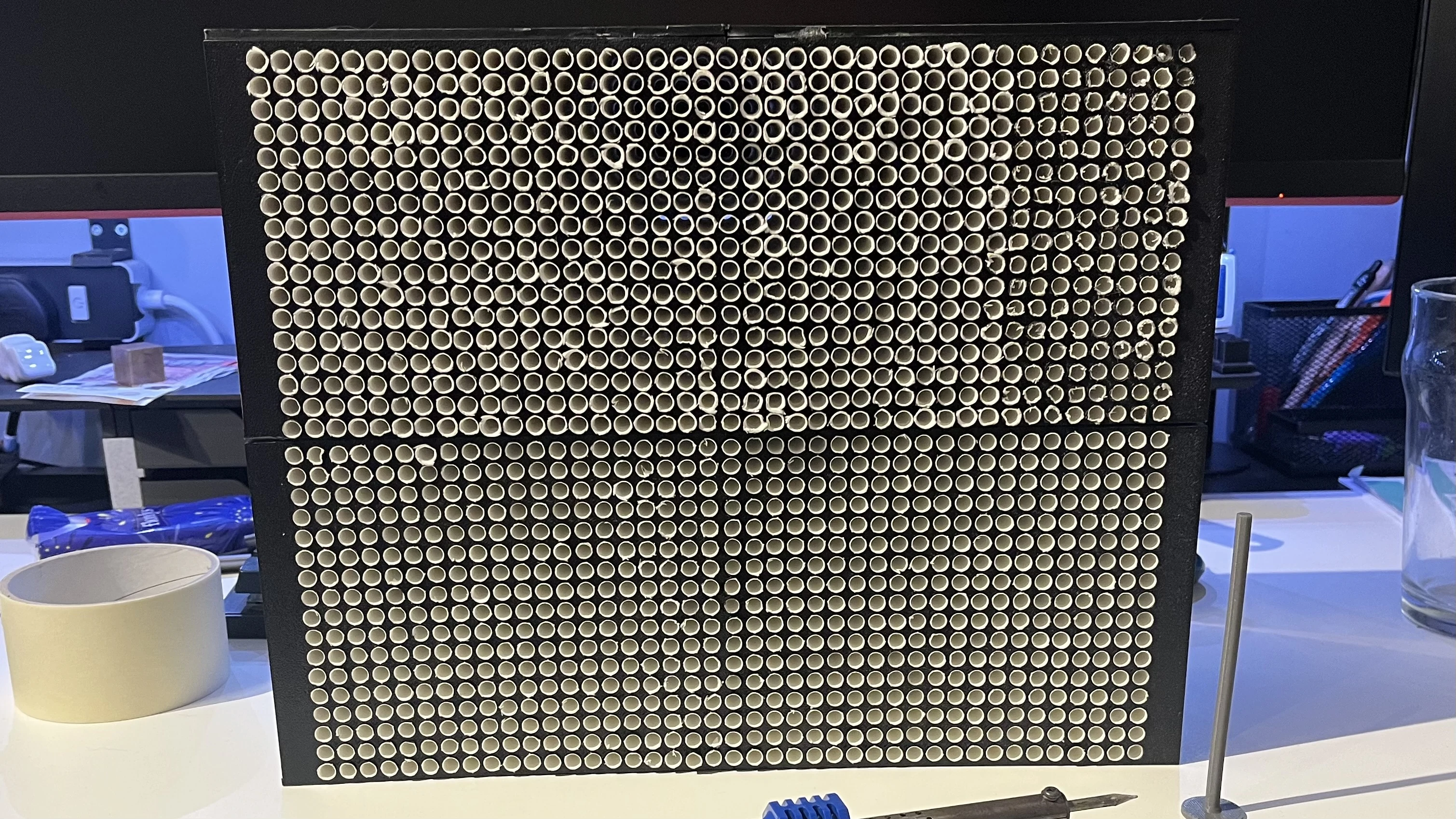
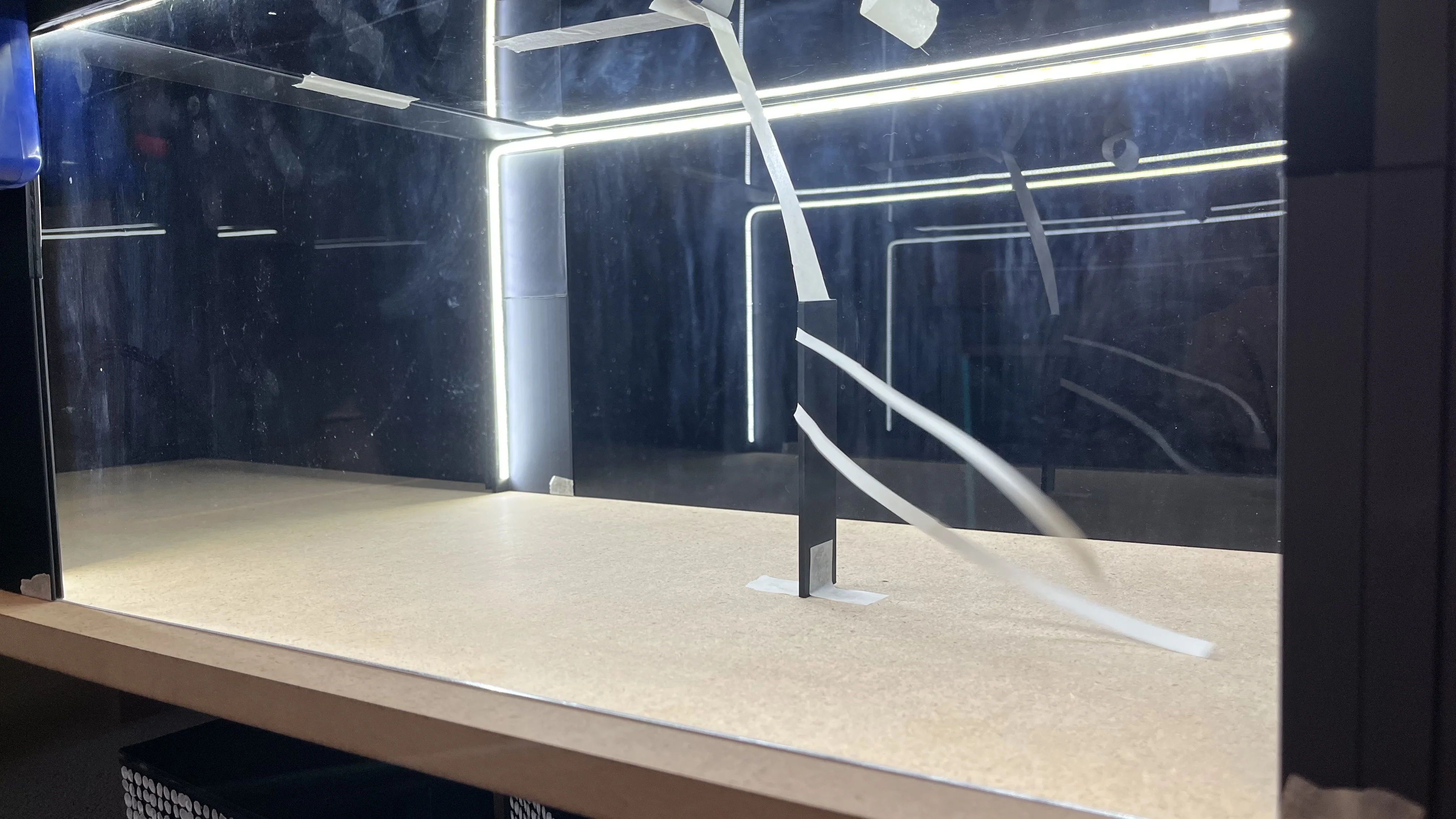
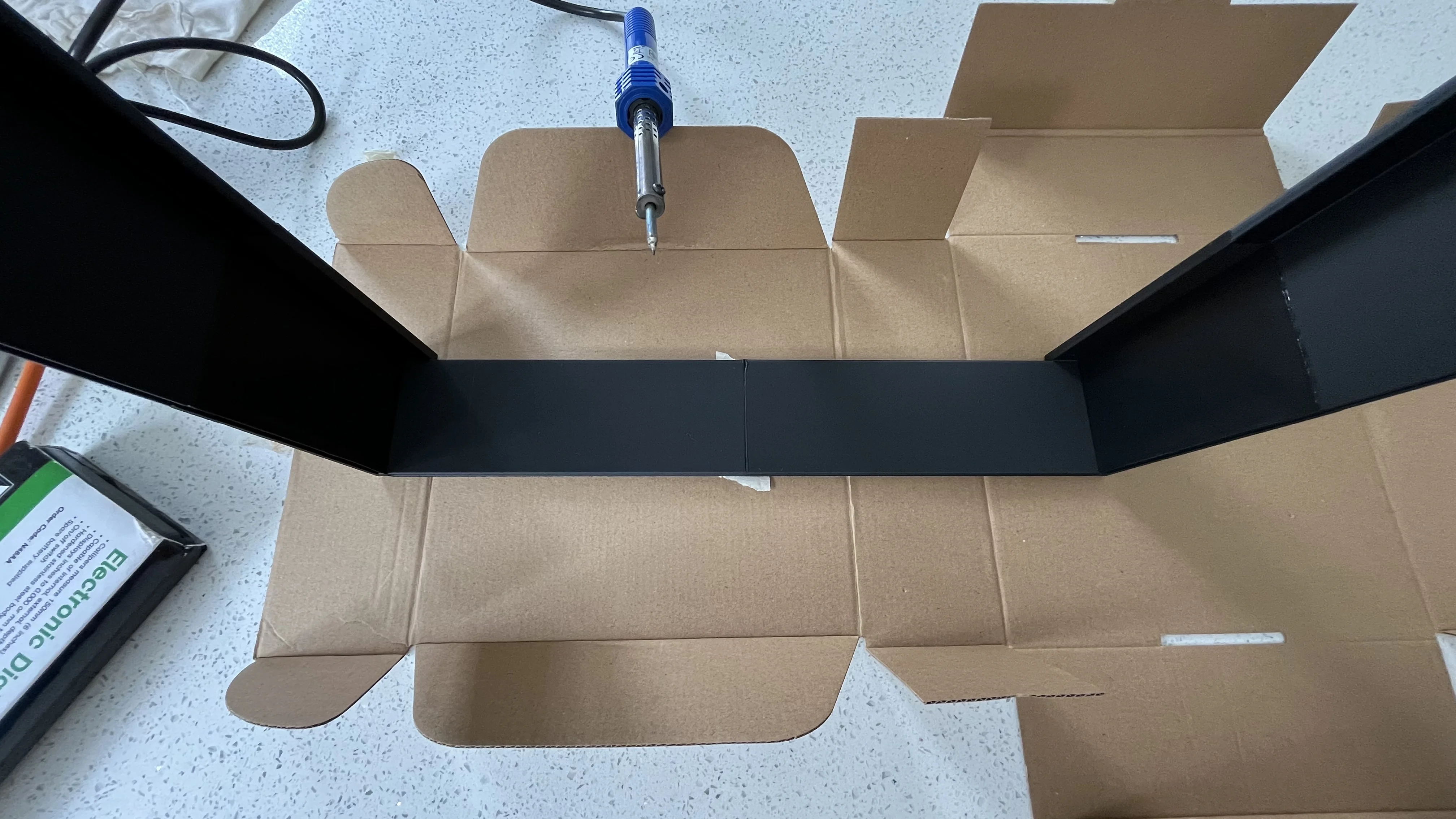
After conducting all of the previous tests and noticing a pattern of imperfect and quite turbulent flow, I began to consider a redesign of the flow system, including moving the fans to the rear of the test section to change the tunnel to a pull configuration. This design would reduce any turbulence from the rear of the fan and would provide cleaner flow in the test section. To validate this, I wanted a tool I could quickly place into the tunnel and test. I designed the structure pictured. The design is made to be as thin as could be reliably printed on my BambuLab A1 Mini, and also to reduce the wake from the frame. The tufts have also been made shorter after I realised that the previous tufts were too long and were moving around due to their delay in reacting to air movement. With shorter tufts, the visual flow was much more believeable and will allow me to compare designs as I begin to prototype them.
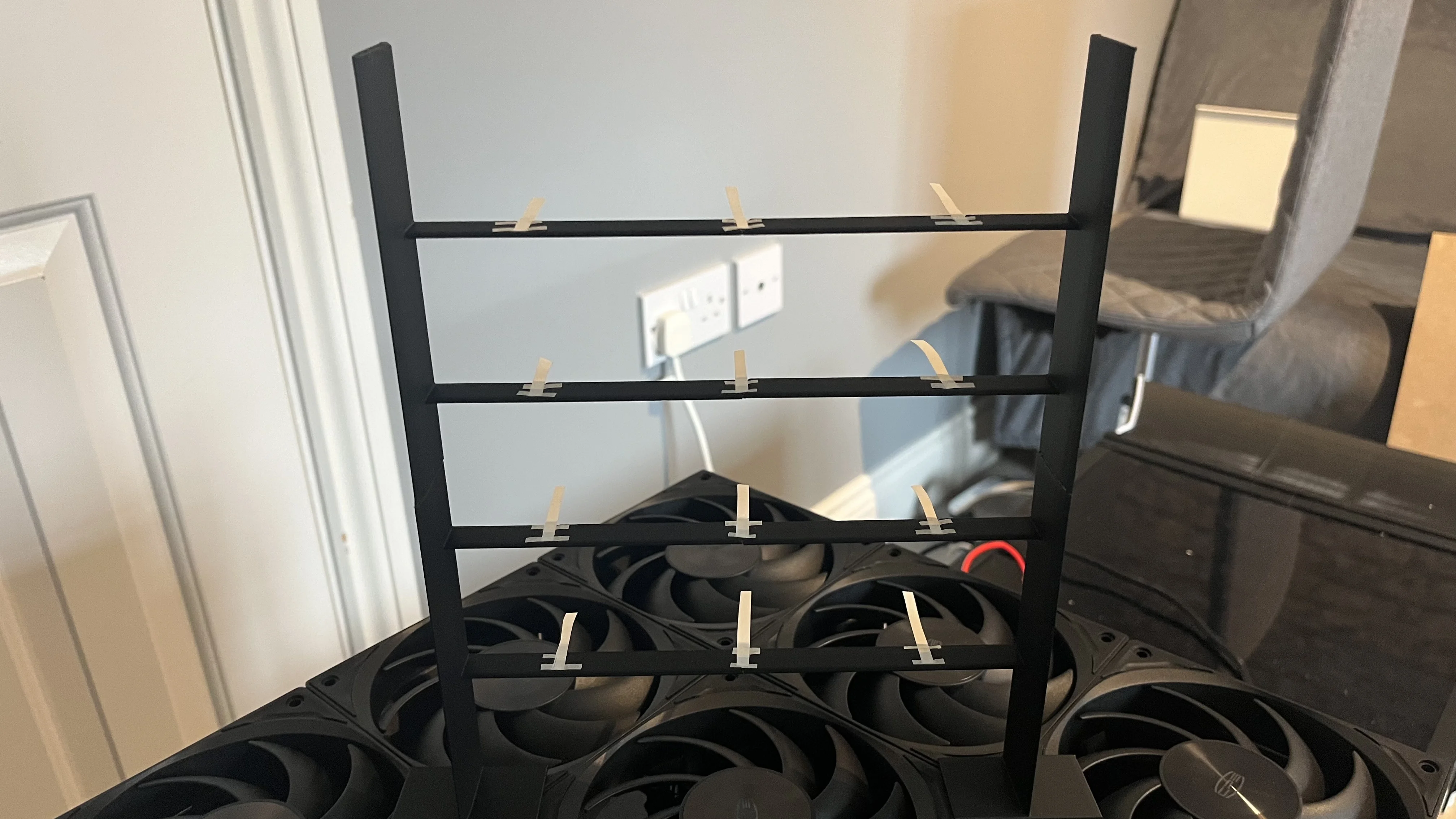
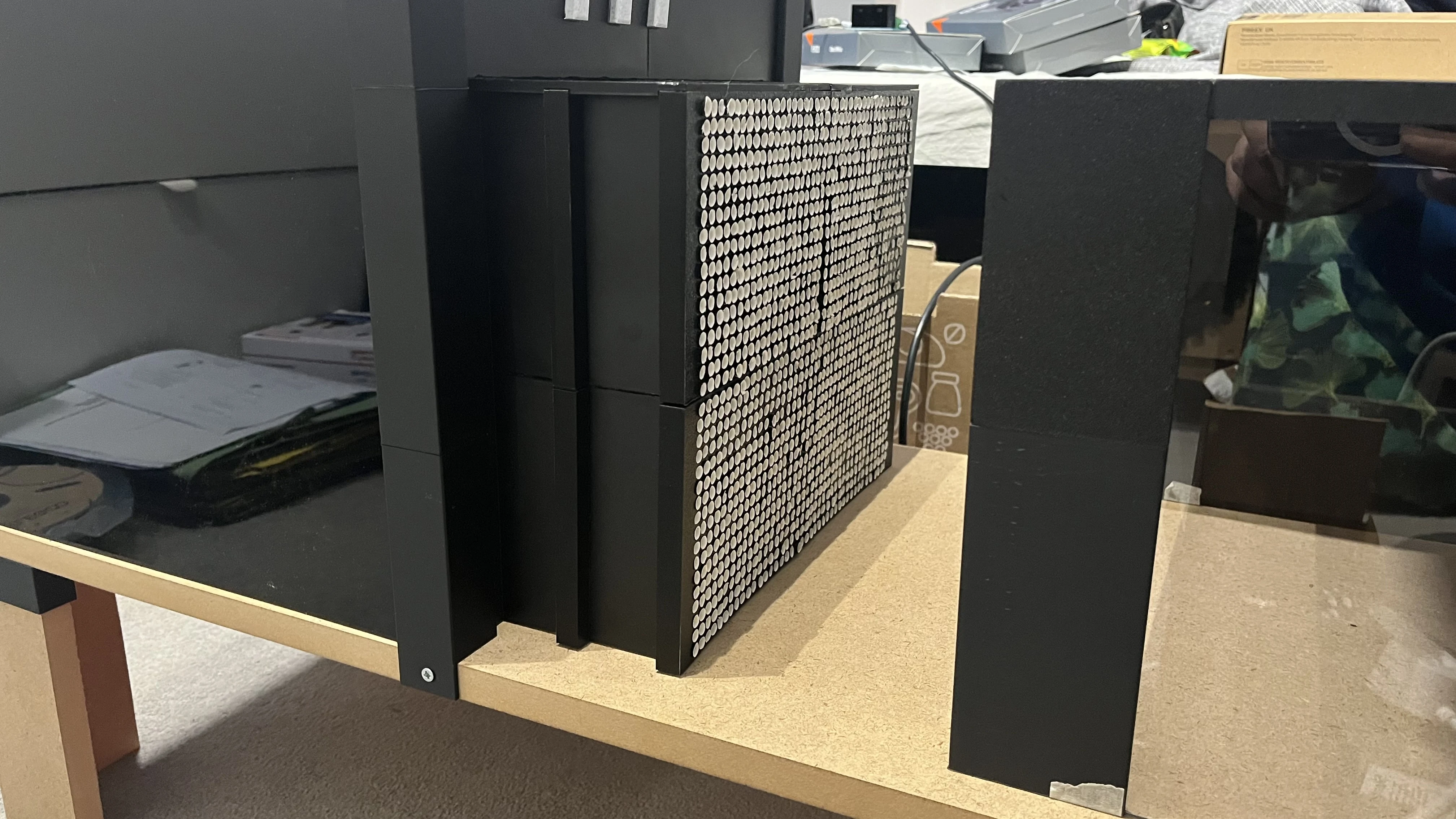
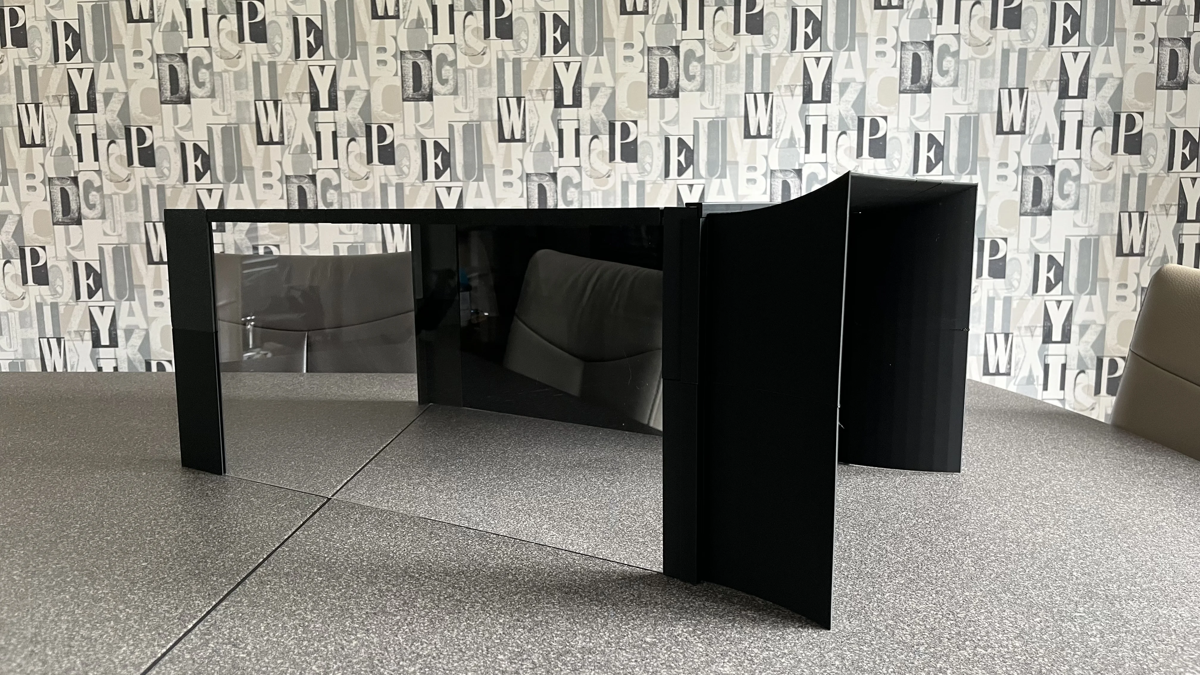
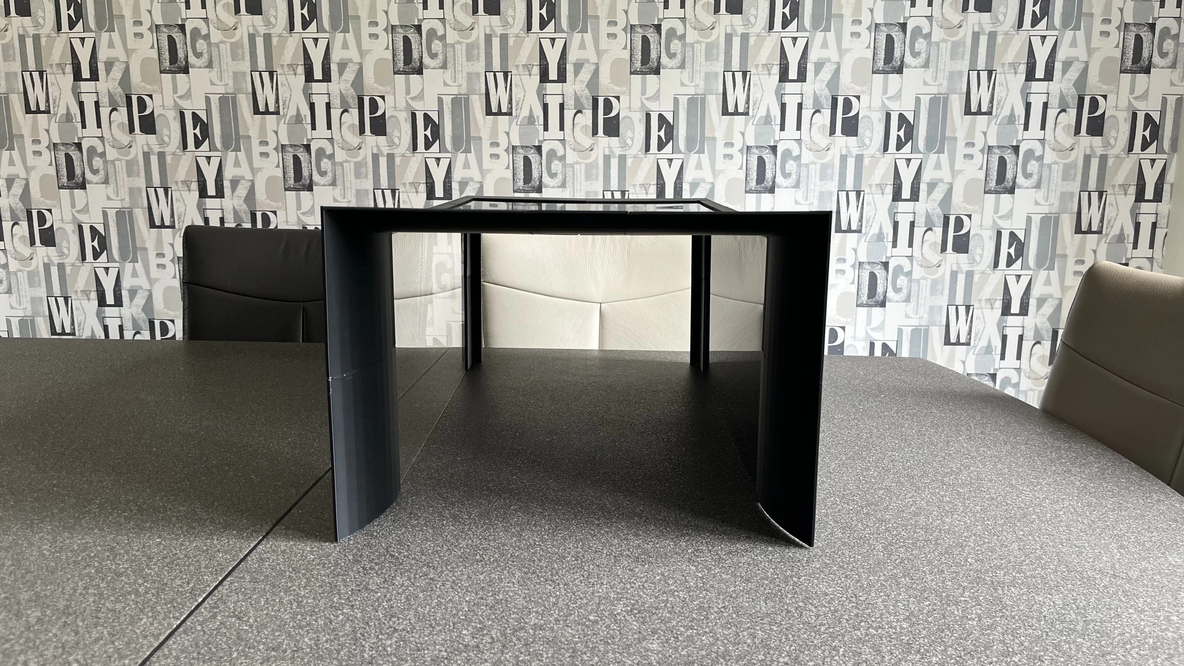
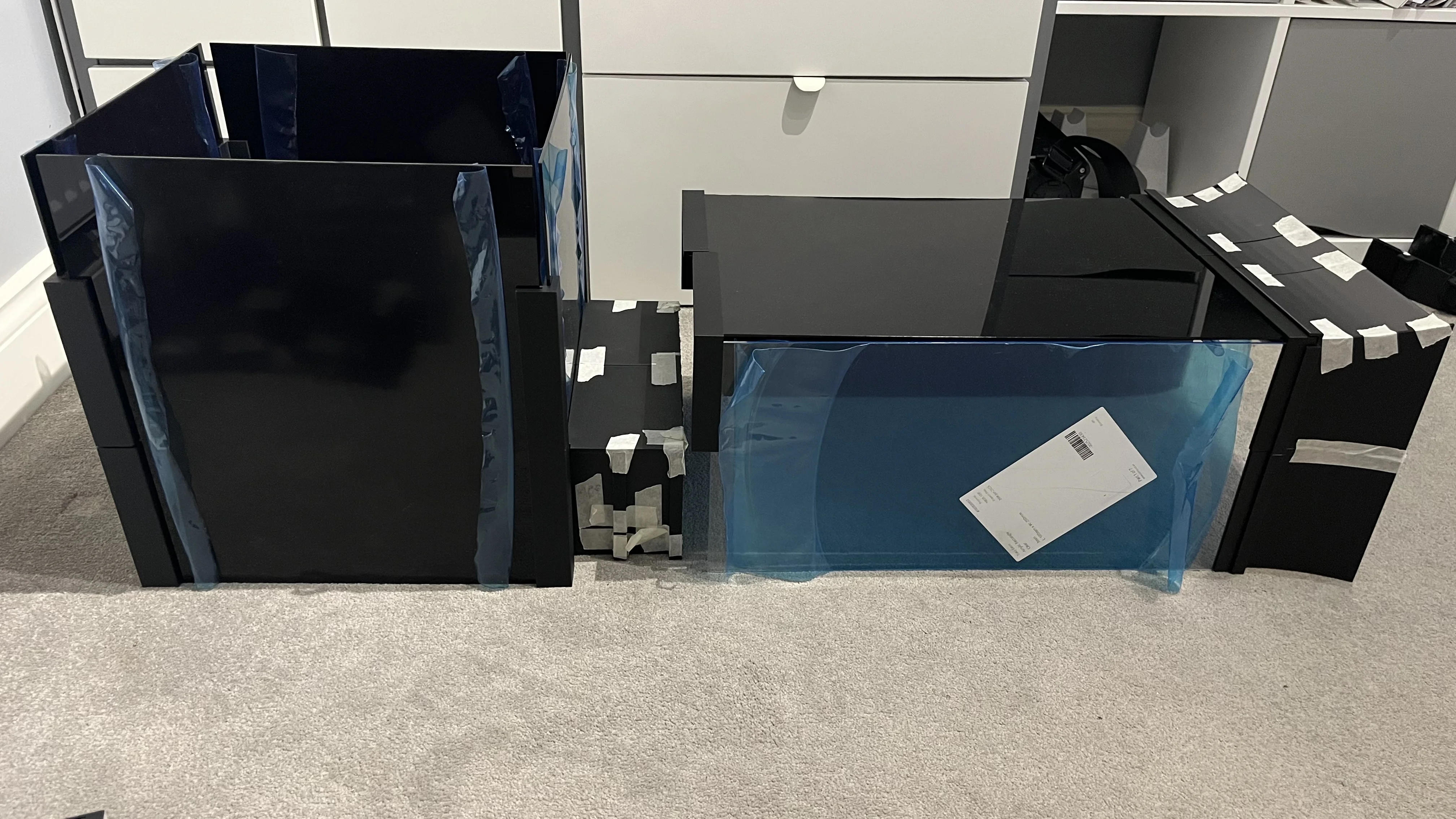
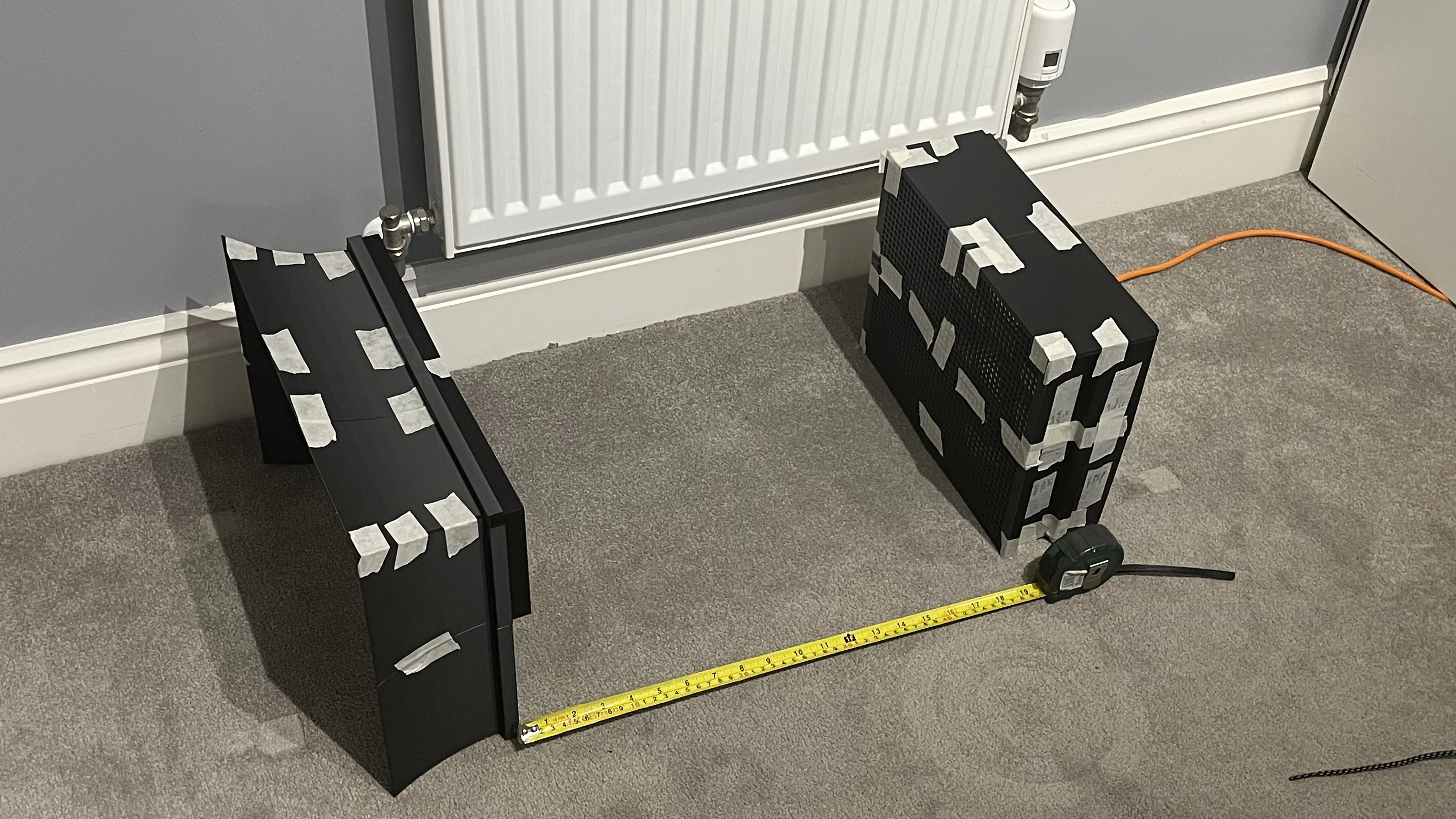
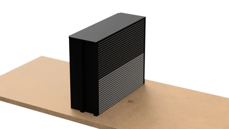
Penultimate tuft testing structure
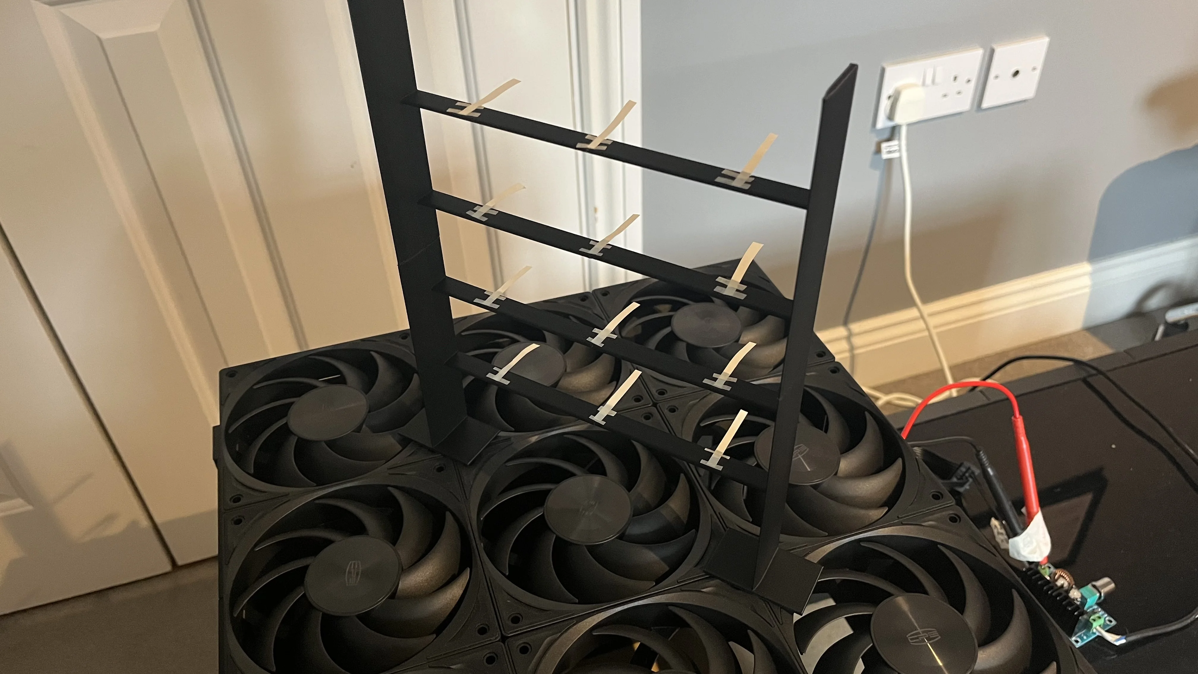
Penultimate tuft testing structure
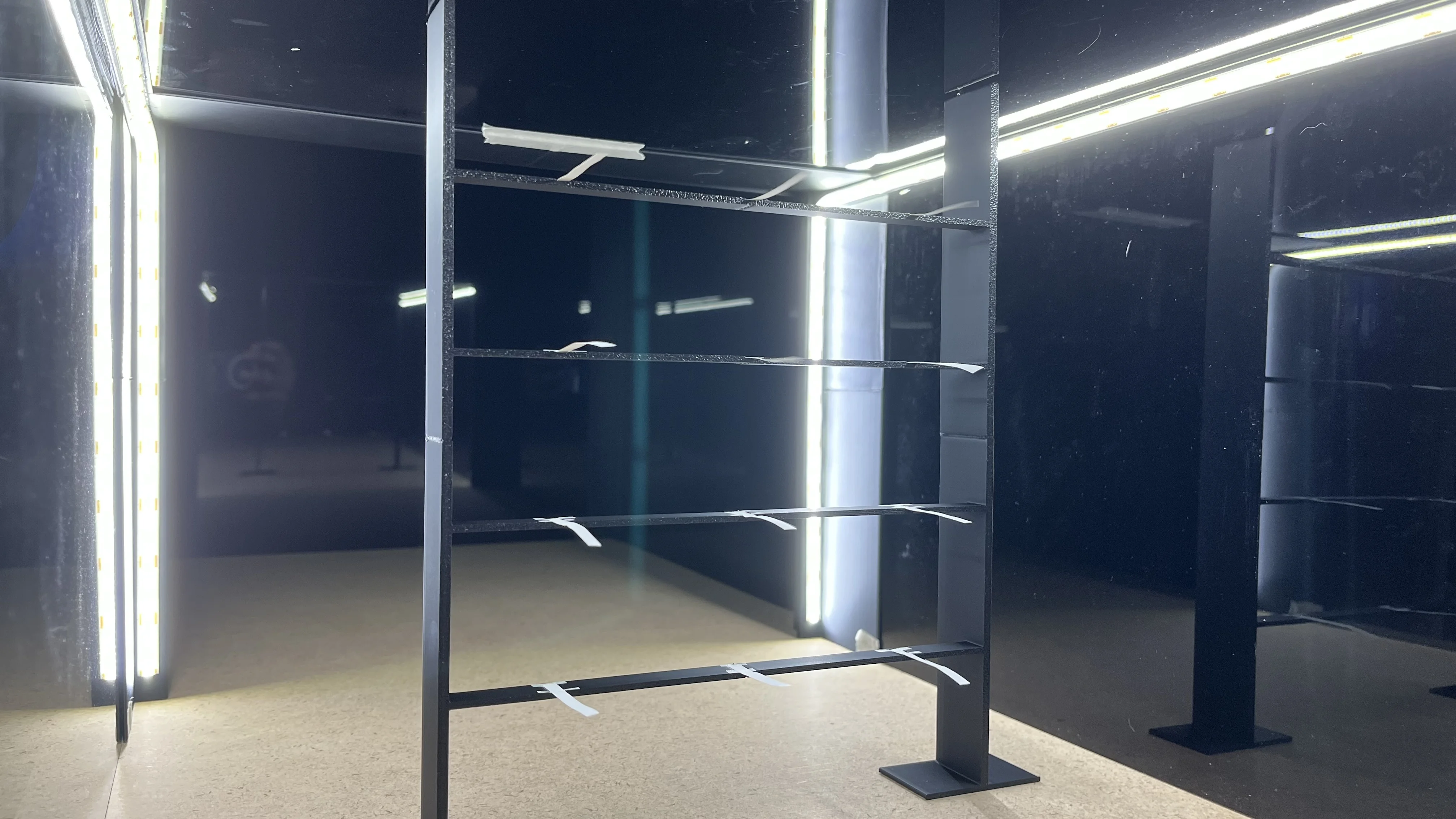
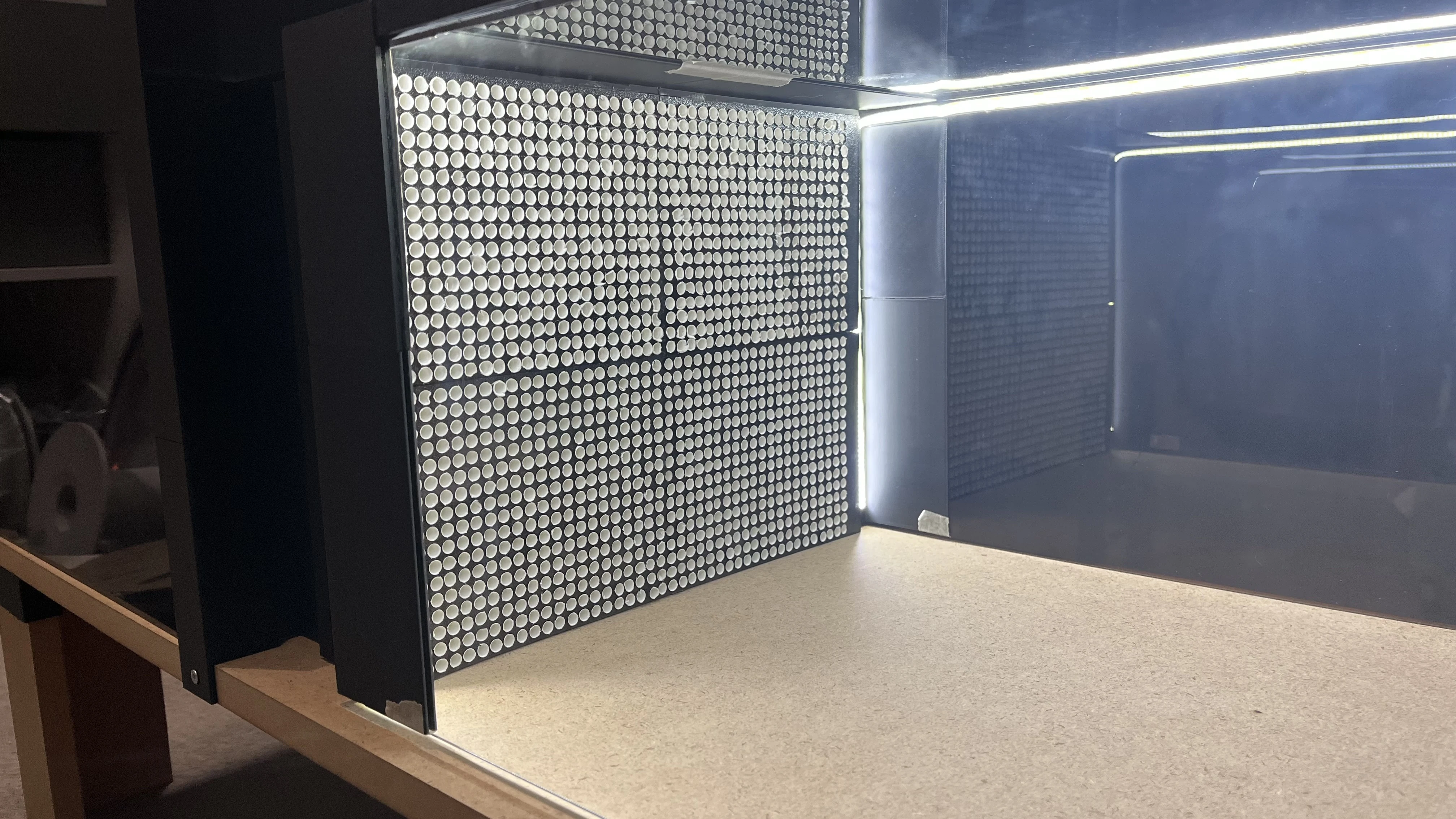
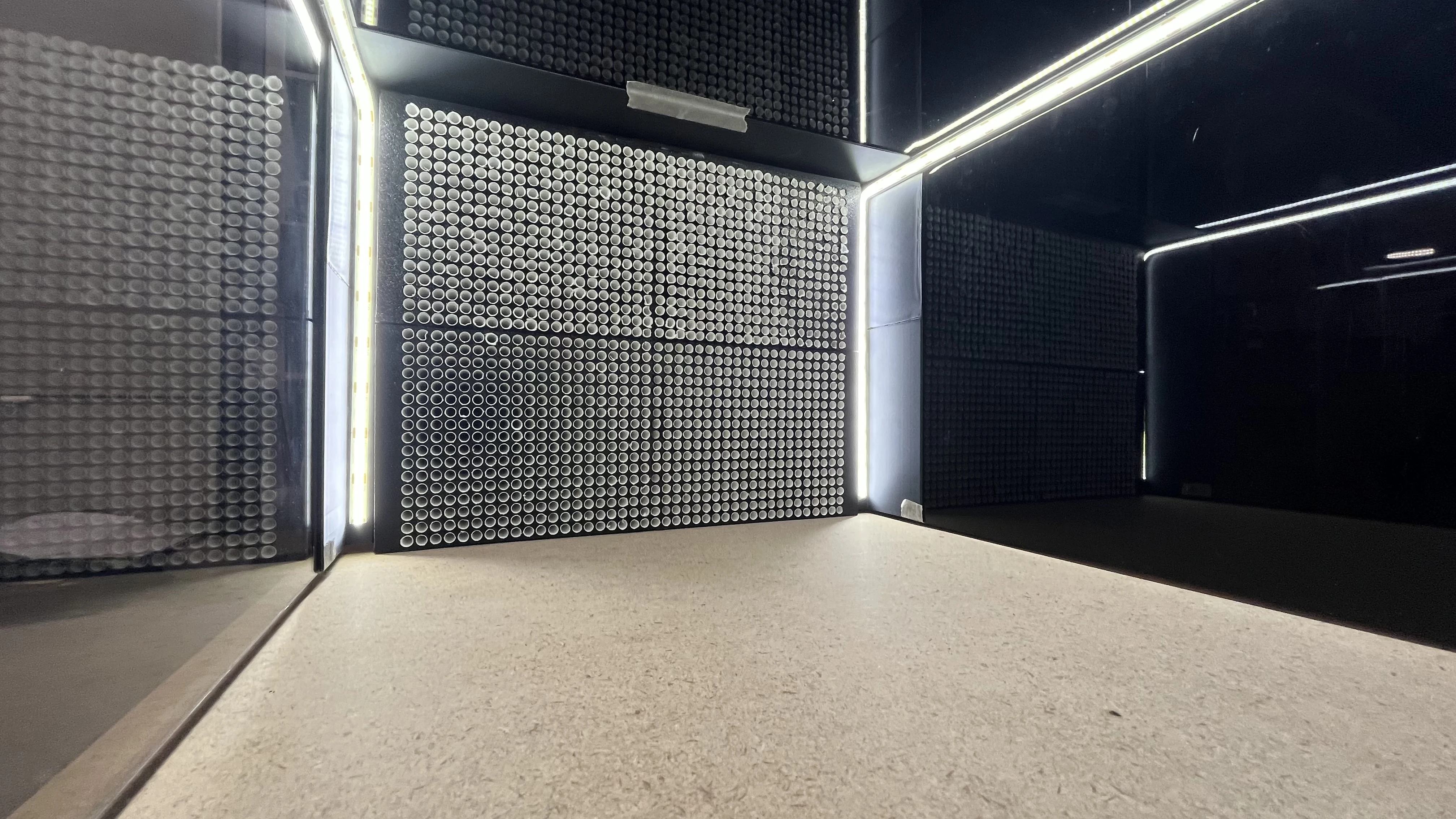
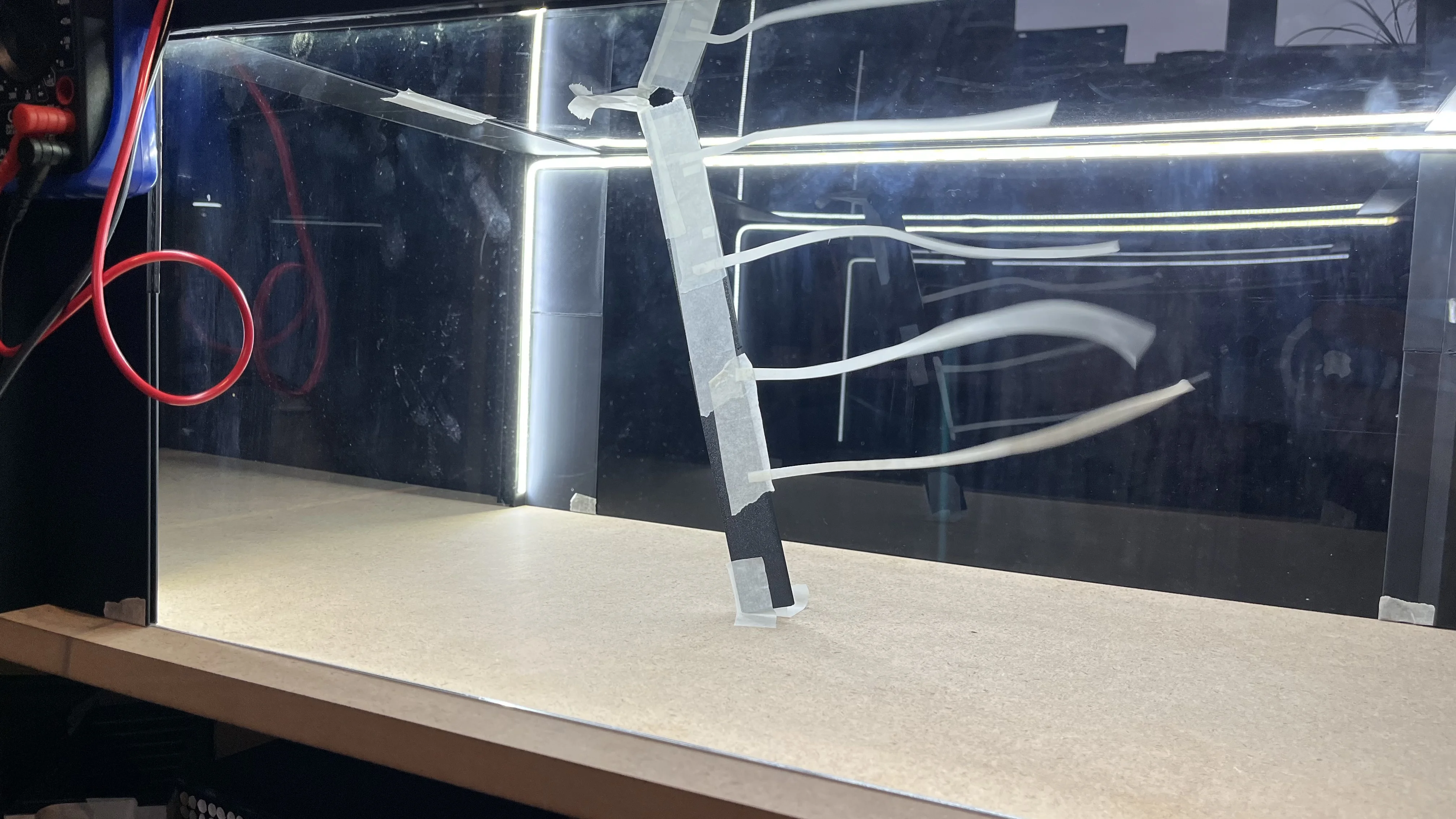
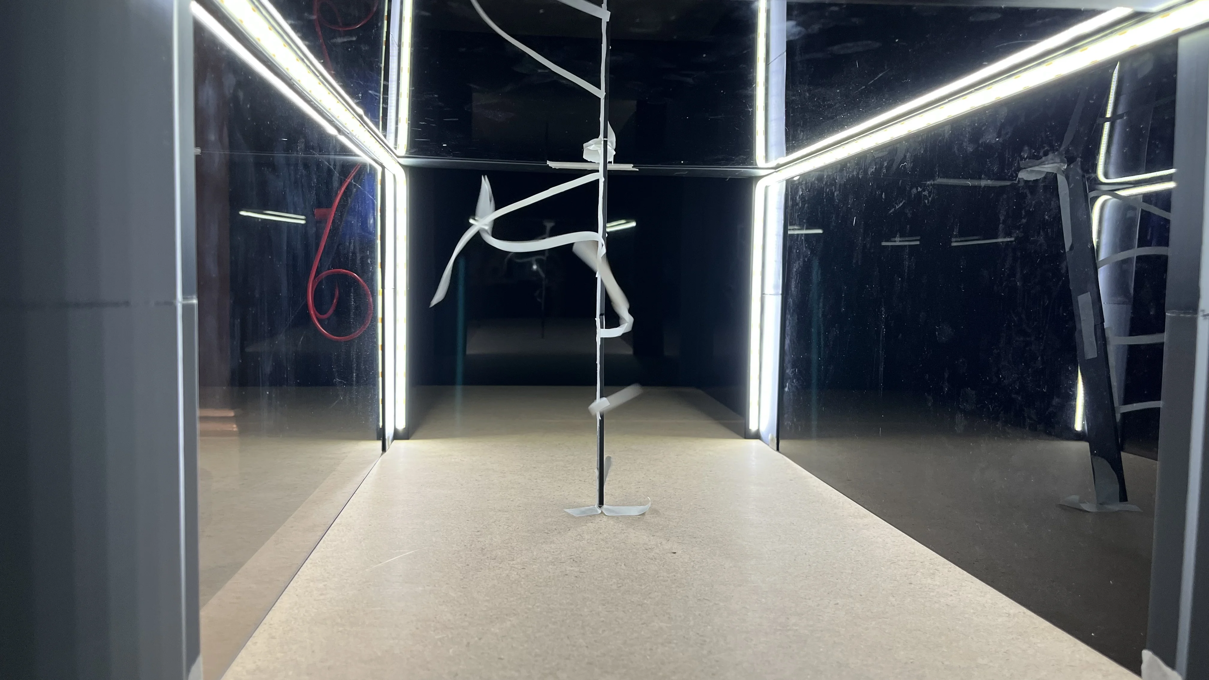
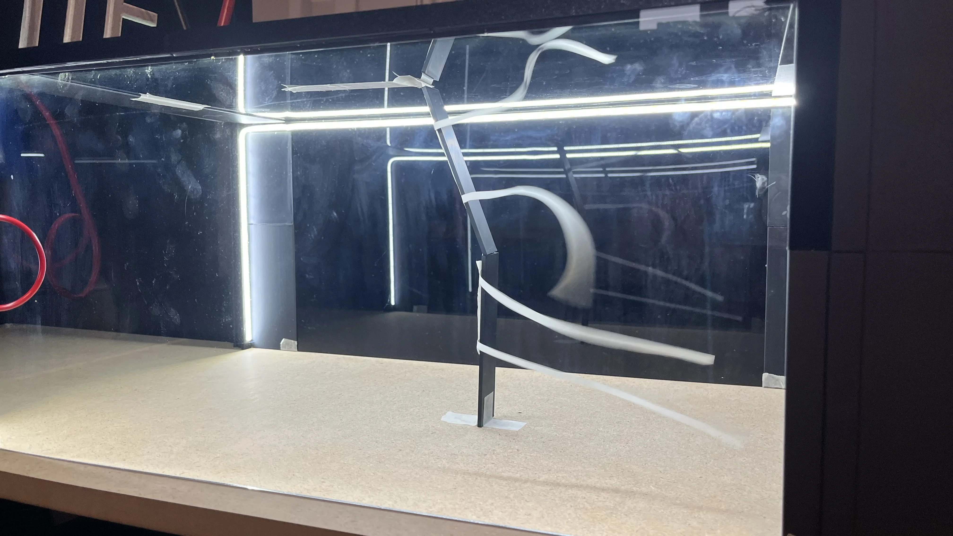
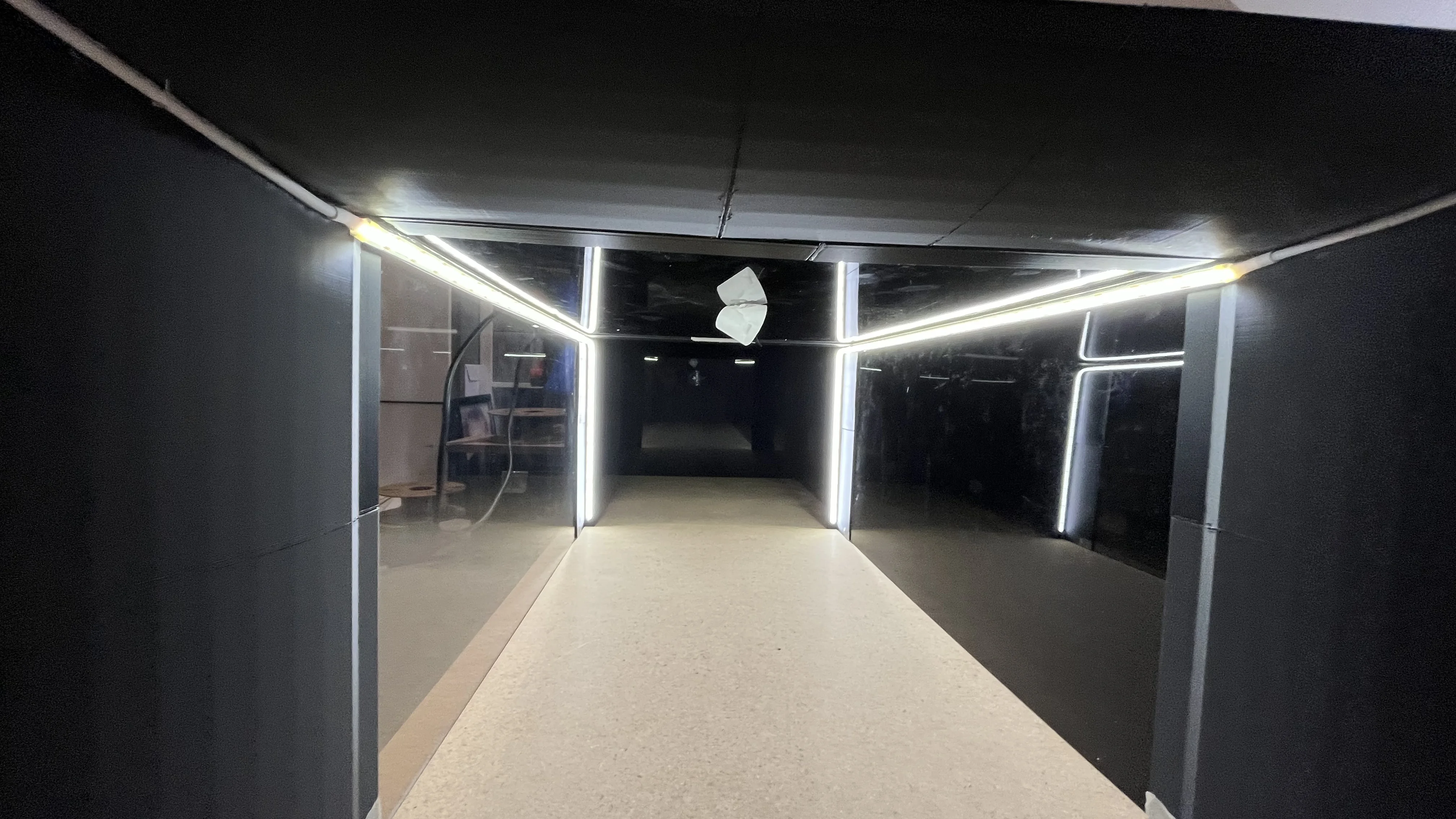
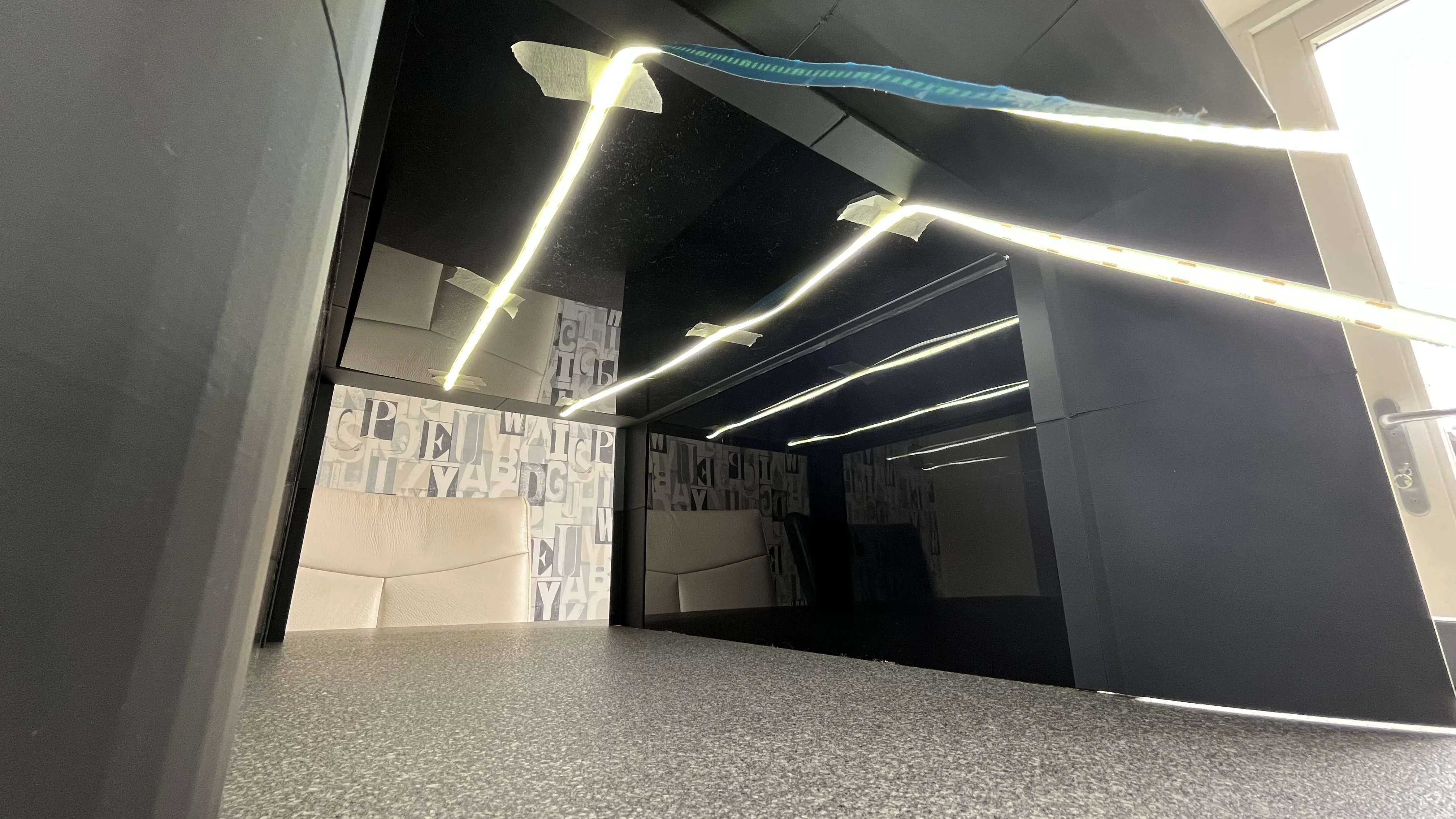
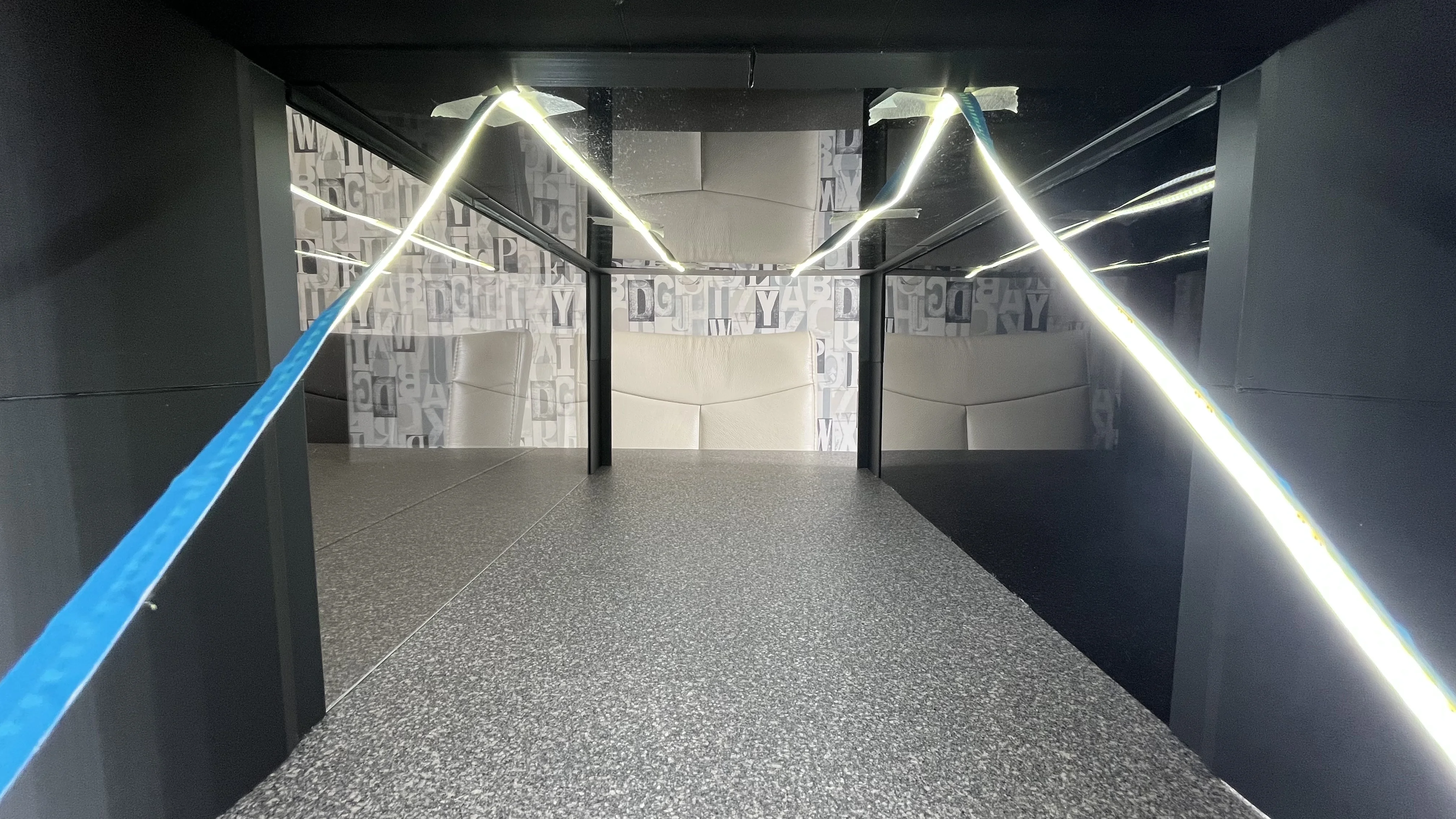
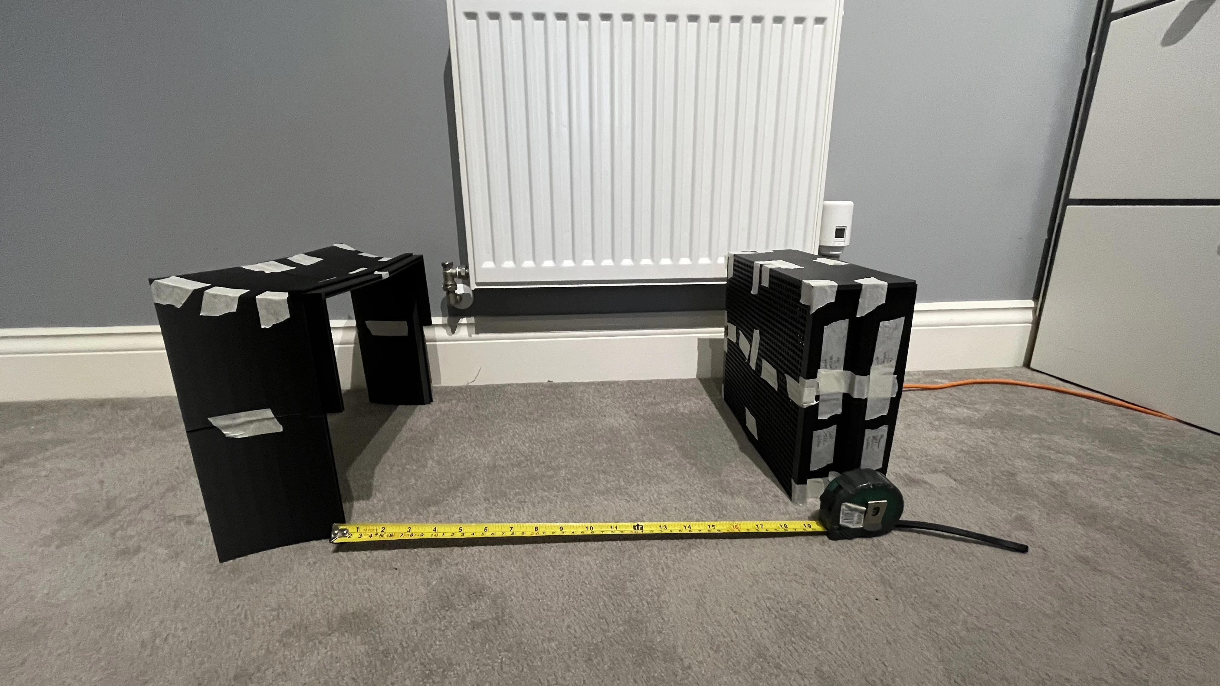
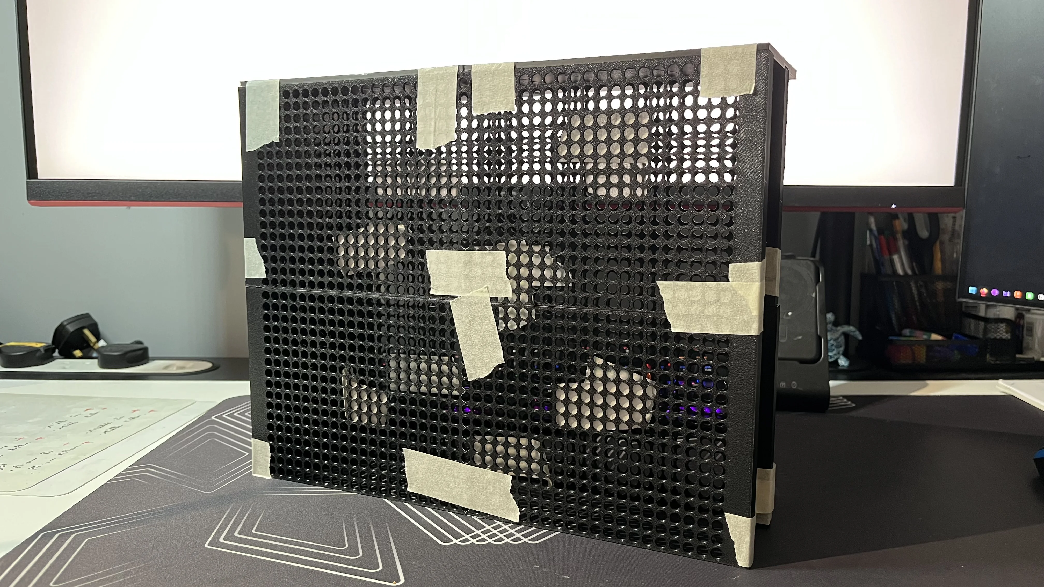
Penultimate tuft testing structure in the wind tunnel
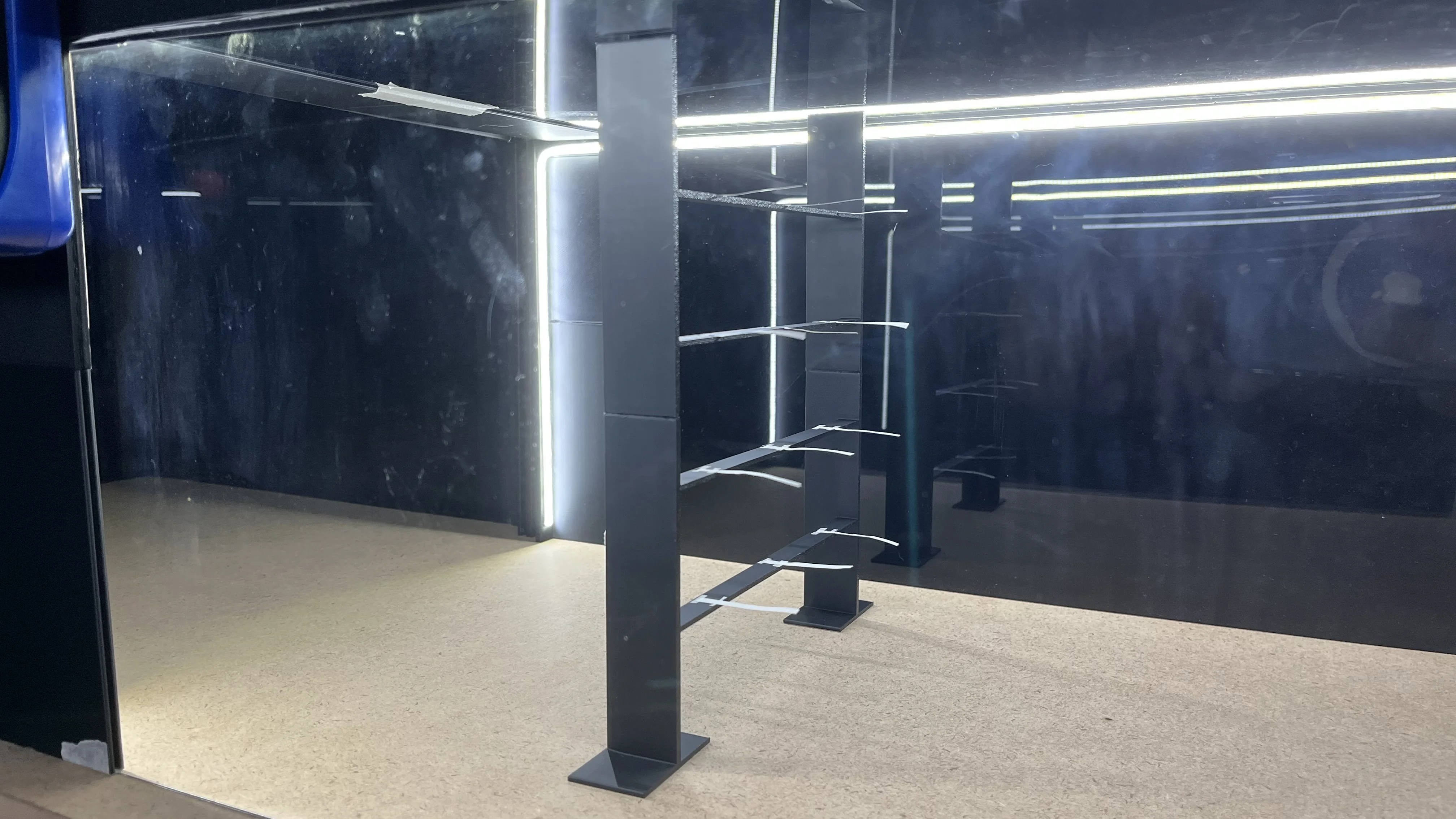
Penultimate tuft testing structure in the wind tunnel
After running the test for a short period, I noticed that the structure was shaking near the top. To fix this, I will fix the structure to the base and top of the tunnel, likely with tape to reduce any vibrations. Also, although the structure is thinner, there will still be a wake around the frame. To reduce this, I plan to suspend thin wire/string between each of the spans and hang the tufts from there. This will reduce the wake as the string/wire will be much thinner and as a result have less imapct o nthe test results.